Serial Port will be very helpful for visualizing the STM32F103C8 peripherals' sensor outputs. Though it is still ok when sensor provides 1-dimension outputs, it will be very hard for human to watch and understand a vector of ouputs changing with time. For example, the outputs from 9-axis motion sensor, Invensense MPU9250 whose outputs include 3-axis gyroscope, a 3-axis accelerometer and 3-axis compass. And some MPU module also includes air pressure sensor Bosch BMP280.
Serial Port can deliver real-time sensor data to host computer (Windows) which uses Python GUI to visualize sensor data streams. And it is what has been done by Invensense eMD software. However, eMD requires an extra USB to Serial (UART) convert to connect STM32 and host computer. Actually, most STM32 chips support USB device mode. It can act as USB CDC ACM device (Serial over USB). So, we don't need any external USB-to-Serial Converter at all.
Prerequisites:
- Keil MDK5 μVision IDE
- STM32F103C8
Step 1: Start a new project in MDK5
Main Menu-> Project-> New μVision Project.
Choose a blank folder for the new project. Click 'Next'
Then a dialog Select Device for Target 'Target 1'... pop-up. Search '103' and you can find that STM32F103C8 appears in device tree. Click 'Ok'.
Step 2: Manage Run-Time Environment
Expand USB->Device in the left most Column'Software Component'
Opt-in 'Core', set Device number to '1', set Device CDC number to '1'. Then, you may notice a list of warning appears at bottom. It is dependence check, since the final application we have just selected relies on other components, such as RTOS::Keil RTX, CMSIS::Core and CMSIS Driver::USB Device, etc.
Expand 'CMSIS->RTOS' and 'CMSIS Driver->USB Device (API)'
And Opt-in the components as shown in figure below:
Then Click 'OK'.
A empty project with many .c and .h files which is related to selected components will be shown.
Step 3: Configuration Wizard: USB
Use configuration wizard to initialize some system and USB parameters
(3.1) In Project browser, Expand 'Target 1'->USB, and double click 'USBD_Config_0.c' to open it.
(3.2) Open tab 'Configuration Wizard'.
(3.3) Change 'Product ID' and 'Product String' to match the info in STM32 USBD CDC driver. I am not sure whether other ID or String matching is needed or not.
RTE Config
Opt-in USB
Step 4: Configuration Wizard: CMSIS->RTX_Conf_CM.c
Set RTX Kernel Time tick to 72MHz (identical to RTE_device.h Clock configuration->System Clock)
Step 5: Add a new file 'USB Device CDC' via User Code Template.
Add define and function declaration to 'USBD_User_CDC_ACM_0.c'
---
#define UART_BUFFER_SIZE 128 // UART Buffer Size
static uint8_t uart_tx_buf[UART_BUFFER_SIZE];
---
// Called when new data was received from the USB Host.
// \param[in] len number of bytes available to read.
void USBD_CDC0_ACM_DataReceived (uint32_t len) {
int32_t cnt;
(void)(len);
//if (ptrUART->GetStatus().tx_busy == 0U) {
// Start USB -> UART
cnt = USBD_CDC_ACM_ReadData(0U, uart_tx_buf, UART_BUFFER_SIZE);
if (cnt > 0) {
//ptrUART->Send(uart_tx_buf, (uint32_t)(cnt));
USBD_CDC_ACM_WriteData(0U, uart_tx_buf, cnt);
}
//}
}
---
Step 6: Add 'main.c' file to 'Source Group 1'
Use User Code Template->CMSIS->RTOS Keil RTX-> CMSIS RTOS 'main' function
Change code to:
---
#include "cmsis_os.h"
#include "rl_usb.h"
---
/*
* main: initialize and start the system
*/
int main (void) {
//osKernelInitialize (); // initialize CMSIS-RTOS
// initialize peripherals here
USBD_Initialize (0U); /* USB Device 0 Initialization */
USBD_Connect (0U); /* USB Device 0 Connect */
// create 'thread' functions that start executing,
// example: tid_name = osThreadCreate (osThread(name), NULL);
//osKernelStart (); // start thread execution
while (1) {
osSignalWait (0U, osWaitForever);
}
}
---
Step 7: Choose 'Menu->Project->Options for Target'
(1) Xtal MHz
My STM32F108C8 uses a 8MHz crystal
(2) Debugger
I uses a very cheap (less than 2 USD) compatible ST-link debugger. In tab 'Debug', choose 'ST-link Debugger'.
Then, click 'Setting' button on the right.
When ST-link is connected to both STM32 mini board and host computer USB, the mini board STM32 chip will be automatically be recognized by MDK5 as show in figure below.
Compiling passes after all these changes. But the work is not yet done. If we just use current object file .axf and load it to STM32 target, USB can't be recognized by host Windows system at all:
It can't get Product ID.
Step 8:
---
//-------- Use Configuration Wizard in Context Menu -----------------
---
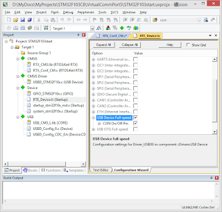
Uncheck High Speed USB
Step 10: Compile and load to STM32
..


1 条评论:
Thanks for your tutorial!
windows can't recognize stm32 "It can't get Product ID." followed all tutorial steps but nothing. I tested with blue pill stm32f103c8t6. can you send me your working keil project or can you check mine?
thanks!
发表评论