2018年4月4日星期三

AI的基本架构(学习笔记)

AI的基本架构


  • AI应用的模型特点

自2010年以来,进入高成熟度状态的是Neural Network分支。对图像、视频、音频、文本为输入的智能处理方面取得的较大的进展。通过超越传统严谨格式的方式,对多样的、或受环境影响、采样条件影响造成畸变,形成的抽象、模糊的数据,进行信号处理。由于信号维度较高,需要大规模信号处理,且统计特性非常复杂,非常规高斯、chi-square、gamma等分布可以进行简单拟合。

如果说1990-2010年的技术突破主要受益于确定的计算,那么在2010至2030年间的主要变革将来自抽象的计算。


  • Neural Network分支的发展

Neural Network 为了与人类或动物大脑区分开,又特称为Artificial Neural Network。
ANN可获得类似MMSE的效果。

针对图像或音频应用,需要引入Domain Specific building block,例如Convolutional layer,用于去噪、对比度增强、边缘提取或角提取,然后在大幅图像中搜索局部特征,由此构成Convolution Neural Network。
CS231n有课件和tensorflow例子。

针对序列信号,可采用Recurrent Neural Network,即对时序信号依次输入,并每一个时刻将上一层输出馈入下一层。由于特定层中所需的输入不一定为前一时刻的输入(Short Term Memory),而是很早前的某个输入(Long Term Memory),RNN可对每个神经元的新输入、历史状态输入、是否更新、是否输出采用门级处理。


  • AI的层组合结构


通常前k层为Domain Specific层,用于提取特征,后面包括Full Connected层,进行高层次(抽象)特征识别,最后可用RNN层,对特征间的高级关联关系进行处理。


  • AI的实用化


经典的AI网络仅神经上的加权系数可通过Back propagation来训练。其基本架构需要超参数来确定,包括各层选用什么类型(Conv, Pooling, FC)等,传导到下一层的Activation Function采用哪种函数(linear,sinc,log,tanh)等。需要炼丹术般的训练。在此训练后,网络缺乏可扩展性,即无法对新类进行辨别,或为新类训练后会忘记老类(灾难性的忘却)。


  • AI的架构自适应
代表作为Google的Progressive Neural Network.


2018年4月3日星期二

What can AI do?

Image recognition
Target Tracking
Tuning Lora Radio
Speech recognition
Robot control

which one is most interesting and valuable?

AI for wireless system
mmWave beam searching and tracking
multi-band CSI fusion (stereo matching)
Joint communication and remote sensing (radar image)
Viterbi decoder and RNN
LSTM and protocol
CNN is similar to LDPC block coding
Polar code channel coding and Attention model

2017年5月7日星期日

I2C connection debug for NodeMCU


---
c1
c2
c3
Device found at address 0x68,sda2,scl4
Device found at address 0x76,sda2,scl4
c4
c5
c6
c7


---
[http://nodemcu.a1w.ca/post/150677174324/use-an-i2c-scanner]
-- This code is public domain, attribution to gareth@l0l.org.uk appreciated.

local pins = {1, 2, 4, 5, 6, 7, 8}
local scl, sda = nil

print("Searching for I2C device")

for scl = 1, 7 do
  for sda = 1, 7 do
    tmr.wdclr()
    if sda ~= scl then
      i2c.setup(0, sda, scl, i2c.SLOW)
      for i = 0, 127 do
        i2c.start(0)
        if i2c.address(0, i ,i2c.TRANSMITTER) then
          print("Device found at address 0x" .. string.format("%02X,sda%d,scl%d", i, sda, scl))
          --print("Device is wired: SDA to GPIO" .. pins[sda] .. " - IO index " .. sda)
          --print("Device is wired: SCL to GPIO" .. pins[scl] .. " - IO index " .. scl)
        else
          --
        end
        i2c.stop(0)
        --print(string.format("%02X,a%d,c%d", i, sda, scl))
      end
    end
  end
  print(string.format("c%d",  scl))
end

---

Accelor Sensor:
The slave address of the MPU-9250 is b110100X which is 7 bits long. The LSB bit of the 7 bit address is determined by the logic level on pin AD0. This allows two MPU-9250s to be connected to the same I2C bus.  When used in this configuration, the address of the one of the devices should be b1101000 (pin AD0 is logic low) and the address of the other should be b1101001 (pin AD0 is logic high).

The reset value is 0x00 for all registers other than the registers below.
• Register 107 (0x01) Power Management 1
• Register 117 (0x71) WHO_AM_I

Magnet Sensor:
WIA reg =00H val =48H


BMP280 Sensor:
The 7-bit device address is 111011x. The 6 MSB bits are fixed. The last bit is changeable by SDO value and can be changed during operation. Connecting SDO to GND results in slave address 1110110 (0x76); connection it to VDDIO results in slave address 1110111 (0x77)


----

id  = 0
sda = 2
scl = 4

-- initialize i2c, set pin1 as sda, set pin2 as scl
i2c.setup(id, sda, scl, i2c.SLOW)

-- user defined function: read from reg_addr content of dev_addr
function read_reg(dev_addr, reg_addr)
    i2c.start(id)
    ack=i2c.address(id, dev_addr, i2c.TRANSMITTER)
    i2c.write(id, reg_addr)
    i2c.stop(id)
    i2c.start(id)
    i2c.address(id, dev_addr, i2c.RECEIVER)
    c = i2c.read(id, 1)
    i2c.stop(id)
    return c,ack
end

-- get content of register 0xAA of device 0x77
reg,ack = read_reg(0x68, 0x75)
print(string.format("%02x",string.byte(reg))) --return 0x73 or 0x71
print(ack)
reg,ack = read_reg(0x68, 0x6B)
print(string.format("%02x",string.byte(reg)))  --return 0x01
print(ack)
reg,ack = read_reg(0x76, 0xD0)
print(string.format("%02x",string.byte(reg))) --return 0x58
print(ack)

2017年5月4日星期四

Serial Port over USB project: STM32F103C8 mini broad + Keil MDK5 IDE - Section 1

Serial Port will be very helpful for visualizing the STM32F103C8 peripherals' sensor outputs. Though it is still ok when sensor provides 1-dimension outputs, it will be very hard for human to watch and understand a vector of ouputs changing with time. For example, the outputs from 9-axis motion sensor, Invensense MPU9250 whose outputs include 3-axis gyroscope, a 3-axis accelerometer and 3-axis compass. And some MPU module also includes air pressure sensor Bosch BMP280.

Serial Port can deliver real-time sensor data to host computer (Windows) which uses Python GUI to visualize sensor data streams. And it is what has been done by Invensense eMD software. However, eMD requires an extra USB to Serial (UART) convert to connect STM32 and host computer. Actually, most STM32 chips support USB device mode. It can act as USB CDC ACM device (Serial over USB). So, we don't need any external USB-to-Serial Converter at all.


Prerequisites:
- Keil MDK5 μVision IDE
- STM32F103C8

Step 1: Start a new project in MDK5

Main Menu-> Project-> New μVision Project.
Choose a blank folder for the new project. Click 'Next'
Then a dialog Select Device for Target 'Target 1'... pop-up. Search '103' and you can find that STM32F103C8 appears in device tree. Click 'Ok'.


Step 2: Manage Run-Time Environment
Expand USB->Device in the left most Column'Software Component'
Opt-in 'Core', set Device number to '1', set Device CDC number to '1'. Then, you may notice a list of warning appears at bottom. It is dependence check, since the final application we have just selected relies on other components, such as RTOS::Keil RTX, CMSIS::Core and CMSIS Driver::USB Device, etc.

Expand 'CMSIS->RTOS' and 'CMSIS Driver->USB Device (API)'
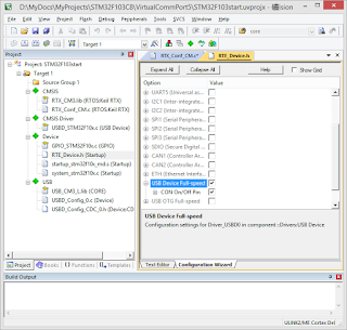
And Opt-in the components as shown in figure below:

Then Click 'OK'.

A empty project with many .c and .h files which is related to selected components will be shown.

Step 3: Configuration Wizard: USB
Use configuration wizard to initialize some system and USB parameters

(3.1) In Project browser, Expand 'Target 1'->USB, and double click 'USBD_Config_0.c' to open it.
(3.2) Open tab 'Configuration Wizard'.


(3.3) Change 'Product ID' and 'Product String' to match the info in STM32 USBD CDC driver. I am not sure whether other ID or String matching is needed or not.

RTE Config
Opt-in USB


Step 4: Configuration Wizard: CMSIS->RTX_Conf_CM.c
Set RTX Kernel Time tick to 72MHz (identical to RTE_device.h Clock configuration->System Clock)

Step 5: Add a new file 'USB Device CDC' via User Code Template.

Add define and function declaration to 'USBD_User_CDC_ACM_0.c'
---

#define  UART_BUFFER_SIZE       128     // UART Buffer Size
static            uint8_t       uart_tx_buf[UART_BUFFER_SIZE];
---

// Called when new data was received from the USB Host.
// \param[in]   len           number of bytes available to read.
void USBD_CDC0_ACM_DataReceived (uint32_t len) {
  int32_t cnt;

  (void)(len);

  //if (ptrUART->GetStatus().tx_busy == 0U) {
    // Start USB -> UART
    cnt = USBD_CDC_ACM_ReadData(0U, uart_tx_buf, UART_BUFFER_SIZE);
    if (cnt > 0) {
      //ptrUART->Send(uart_tx_buf, (uint32_t)(cnt));
USBD_CDC_ACM_WriteData(0U, uart_tx_buf, cnt);
    }
  //}
}
---

Step 6: Add 'main.c' file to 'Source Group 1'
Use User Code Template->CMSIS->RTOS Keil RTX-> CMSIS RTOS 'main' function

Change code to:

---
#include "cmsis_os.h"
#include "rl_usb.h"
---
/*
 * main: initialize and start the system
 */
int main (void) {
  //osKernelInitialize ();                    // initialize CMSIS-RTOS

  // initialize peripherals here
  USBD_Initialize (0U); /* USB Device 0 Initialization */
  USBD_Connect (0U); /* USB Device 0 Connect */
  // create 'thread' functions that start executing,
  // example: tid_name = osThreadCreate (osThread(name), NULL);

  //osKernelStart ();                         // start thread execution
 while (1) {
    osSignalWait (0U, osWaitForever);
  }
}
---

Step 7: Choose 'Menu->Project->Options for Target'
(1) Xtal MHz
My STM32F108C8 uses a 8MHz crystal
(2) Debugger
I uses a very cheap (less than 2 USD) compatible ST-link debugger. In tab 'Debug', choose 'ST-link Debugger'.
Then, click 'Setting' button on the right.

When ST-link is connected to both STM32 mini board and host computer USB, the mini board STM32 chip will be automatically be recognized by MDK5 as show in figure below.


Compiling passes after all these changes. But the work is not yet done. If we just use current object file .axf and load it to STM32 target, USB can't be recognized by host Windows system at all:
It can't get Product ID.

Step 8:

---
//-------- Use Configuration Wizard in Context Menu -----------------

 ---

Uncheck High Speed USB


Step 10: Compile and load to STM32

..

2015年11月3日星期二

ESP8266 WiFi IoT Chip


1 Overview
Table of Contents
[Complete Listing of Documentation Released]


Environment
进行软件二次开发,请先下载并安装编译环境
注:密码是 qudl

2. Firmwares
[[RTOS SDK Release] ESP8266_RTOS_SDK_V1.3.0_15_11_02]
[]


esp_iot_sdk 软件是最基本的
IOT_Demo 和 AT 的编译都基于它。
2、IOT_Demo 位于软件包中 "examples" 文件夹,给出三种物联网设备“智能开关”,“灯”,“传感器”的简单demo,三种设备在user_config.h 中定义,请每次只使能一种设备调试~
3、AT 是另一个应用demo,示范 ESP8266 作为 slave 外接一个 Host,Host 通过 AT 指令控制 ESP8266 联网传数据等操作。
4、AT 是与 IOT_Demo 同一级别的应用demo,请勿同时拷贝到文件夹“app” 编译。未改动代码的情况下,要么作为独立运行的 IOT_Demo,要么作为附属 wifi 功能的 AT

3. Subsystem
MAC
Power Saving
[Features:light-sleep and deep-sleep under sdkV0.9.5]


4. Application based on Lua
[http://bbs.nodemcu.com/t/nodemcu/104]
connect usb cable to dev broad.
turn off the wifi card power switch
take off flash firmware cap
 open "ESP8266烧录工具/frame_test.exe"
choose the firmware to be flash
click start flash
turn on the wifi card power switch

  1. Example 1:
use putty to connect to the broad
try hello world example

> print("hello,world!")
stdin:1: unexpected symbol near 'char(27)'
> print("a")
a
> print("hello,world!")
hello,world!


Example 2:
try wifi connection

> print(wifi.sta.getip())
stdin: bad header in precompiled chunk
> print(wifi.sta.getip())
stdin: bad header in precompiled chunk
> print(wifi.sta.getip())
nil
> wifi.setmode(wifi.STATION)
> wifi.sta.config("AP name","password")
> print(wifi.sta.getip())
nil
> print(wifi.sta.getip())
nil
> wifi.setmode(wifi.STATION)
stdin:1: unexpected symbol near 'char(3)'
> wifi.setmode(wifi.STATION)
> wifi.sta.config("AP name","password")
> print(wifi.sta.getip())
stdin:1: unexpected symbol near 'char(3)'
> print(wifi.sta.getip())
192.168.18.246  255.255.255.0   192.168.18.1


C:\>ping 192.168.18.246 -t

Pinging 192.168.18.246 with 32 bytes of data:
Reply from 192.168.18.246: bytes=32 time=173ms TTL=255
Reply from 192.168.18.246: bytes=32 time=176ms TTL=255

Ping statistics for 192.168.18.246:
    Packets: Sent = 2, Received = 2, Lost = 0 (0% loss)
Approximate round trip times in milli-seconds:
    Minimum = 173ms, Maximum = 176ms, Average = 174ms


Example 3:

lua code:
srv=net.createServer(net.TCP) 
srv:listen(80,function(conn) 
    conn:on("receive",function(conn,payload) 
    print(payload) 
    conn:send("

Hello, NodeMCU.

"
) end) end)

Upload Lua code via Nodemcu studio
[Nodemcu Studio 2015 build20150111.rar]

visit [http://192.168.18.246/] in browser
you can see text in browser
"

Hello, NodeMCU.

"

and in console, you will see:
> dofile("simplehttpserver.lua")
> GET / HTTP/1.1
Host: 192.168.18.246
User-Agent: Mozilla/5.0 (Windows NT 6.3; WOW64; rv:42.0) Gecko/20100101 Firefox/42.0
Accept: text/html,application/xhtml+xml,application/xml;q=0.9,*/*;q=0.8
Accept-Language: en-US,en;q=0.5
Accept-Encoding: gzip, deflate
Connection: keep-alive

visit [http://192.168.18.246/addressCode] in browser

GET /addressCode HTTP/1.1
Accept: text/html, application/xhtml+xml, */*
Accept-Language: en-US,en;q=0.8,zh-Hans-CN;q=0.5,zh-Hans;q=0.3
User-Agent: Mozilla/5.0 (Windows NT 6.3; WOW64; Trident/7.0; Touch; rv:11.0) like Gecko
Accept-Encoding: gzip, deflate
Host: 192.168.18.246
DNT: 1
Connection: Keep-Alive


 Example 4

Use http request in browser to control gpio (light)

pin=0
gpio.mode(pin,gpio.OUTPUT)
lightOn=0
srv=net.createServer(net.TCP)
srv:listen(80,function(conn)
    conn:on("receive",function(conn,payload)
    print(payload)
    if lightOn==0 then
        lightOn=1
        gpio.write(pin,gpio.HIGH)
    else
        lightOn=0
        gpio.write(pin,gpio.LOW)
    end
    conn:send("

Hello, NodeMCU.

")
    end)
end)


2015年10月26日星期一

Emerging directions

新兴行业

RTL-SDR 侦听LoRa通信 GNU 解码LoRa包

网络分析:NS3 www.nsnam.org

文档结构可视化 自动化关联分析python
协议交互行为+信息可视化

人工智能, Machine Learning, First Order Logic,Statistical Learning

视频目标跟踪 c

机器人制造:遥控赛车,嵌入式ARM Cortex-M3 Launchpad,电机控制

2011年10月1日星期六

触手

章鱼的触手的每一小段都有触觉,如果线缆也能这样那么就帮了无线通信大忙。如果信号能够在需要的那一段被释放出去,信号就能集中给用户,并抑制干扰的产生。

现存的无线系统依赖于天线和线缆。线缆把信号束缚于其中,让能量集中在一起。天线将信号散播开。由于无线通信对端位置的不确定,我们需要利用分集的思想,降低outage的概率。所以,我们用多条传输线,连接多条线缆。当多条传输线共用相当长的一段传输路线时,比如多根天线都部署在高塔上,复用一根线缆,将信号引上塔顶,然后解复用显然是一个简洁的设计,能够节省成本,Nortel申请了这项专利。而在其他情况下,多根天线将以其他的方式共用的一段传输路线,比如在室内部署中,沿着狭长的走廊两端有很多房间。这样,每隔一段距离,就需要向上并接或向下分支一部分信号。如果能像主干的光纤系统那样,利用频域或时域特性来汇聚信号,来建立Distributed Antenna System,并结合先进信号检测技术,限制容量的干扰问题就可以解决。

Things to be done:简单的上下载变频器件。